Glossary of Terms
The following table defines the common variables and symbols used in the BJSFM API and theoretical formulations, based on Lekhnitskii’s anisotropic plate solutions.
Basic Laminate & Geometry
| Term | Description |
|---|---|
| t / h | Laminate / plate thickness. |
| r | Hole radius. |
| a | Extensional stiffness matrix [A] from Classical Lamination Theory (CLT). In the Lekhnitskii module, a refers to the inverse [A] matrix. |
| a_inv | Inverse of the [A] matrix, representing the laminate compliance. |
Complex Roots & Mapping Parameters
| Term | Description |
|---|---|
| μ₁, μ₂ (mu1, mu2) | Real part of the first and second roots of the characteristic equation for the anisotropic plate. |
| μ̅₁, μ̅₂ (mu1_bar, mu2_bar) | Imaginary part of the first and second roots of the characteristic equation. |
| ξ₁, ξ₂ (xi_1, xi_2) | First and second mapping parameters used to transform the complex plane geometry into a unit circle. |
Stress Functions & Load Terms
| Term | Description |
|---|---|
| Φ₁, Φ₂ (phi_1, phi_2) | First and second complex stress functions satisfying the governing boundary conditions. |
| Φ'₁, Φ'₂ (phi_1_prime, phi_2_prime) | Derivatives of the first and second stress functions. |
| A, B (A, B) | Real parts of the equilibrium constants for the first and second stress functions. Accounts for unbalanced bearing loads reacting at infinity. |
| A̅, B̅ (A_bar, B_bar) | Imaginary parts of the equilibrium constants for the first and second stress functions. |
| α, β (alpha, beta) | Fourier series coefficients modified for use in stress function equations representing applied far-field stresses or bearing distributions. |
Bearing Load & Distribution
| Term | Description |
|---|---|
| P | Applied bearing force. |
| P_c | Peak radial bearing pressure assuming a cosine distribution over half the hole. P_c = 4*P / (π*d*t) |
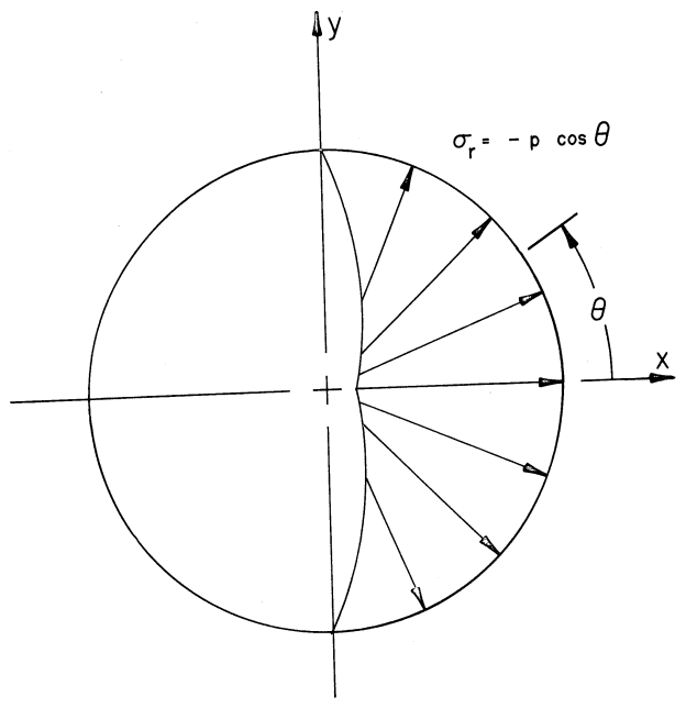
| θ (theta) | Angular position around the hole perimeter, measured from the x-axis. |
| α (alpha_angle) | Direction of the applied bearing load (typically 0° for x-bearing or 90° for y-bearing). |
The standard bearing pressure distribution used in BJSFM is p(θ) = P_c * cos(θ - α) applied over the contact angle from -π/2 to +π/2 relative to the bearing load direction α.