
Loading Configuration
The loading configuration defines the mechanical environment around the fastener hole. All loads are specified as running loads (force per unit width, lb/in) or moments.
Fastener Parameters
| Parameter | Units | Description |
|---|---|---|
| Diameter | in | Fastener hole diameter |
| Joint Type | — | Single-shear or Double-shear. Affects the load transfer distribution. |
| e/D | — | Edge distance ratio. Used for finite-width correction factors. |
| Countersink Depth | in | Depth of countersink from the tool-side surface. Set to 0 for protruding head fasteners. |
Bearing Loads
Bearing loads represent the contact force between the fastener shank and the hole wall. They are input as running loads in the x and y directions (lb/in).
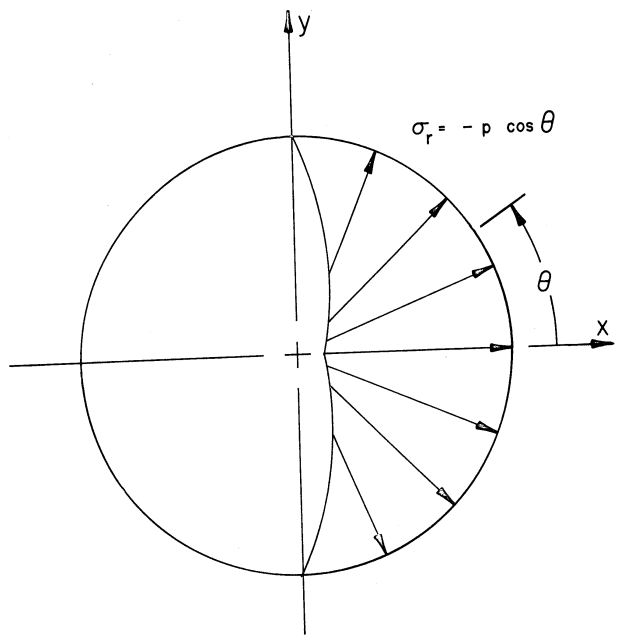
Internally, the bearing load is applied as a cosine pressure distribution over the contact arc on the hole boundary. The bearing load magnitude determines the peak pressure.
Bypass Loads
Bypass loads are the far-field running loads that “bypass” the fastener — they represent the portion of the panel load not transferred through the bolt. These are entered as:
- Nx — Running load in the x-direction (lb/in)
- Ny — Running load in the y-direction (lb/in)
- Nxy — In-plane shear running load (lb/in)
Optional bypass moments (Mx, My, Mxy) can also be applied for bending effects.
Number of Points
Controls the angular resolution of the hole-boundary stress evaluation. The default of 36 points corresponds to 10° increments around the hole (0° to 350°).
Increasing the number of points gives finer resolution but slightly increases computation time. For most analyses, 36 points is sufficient to capture peak stresses.