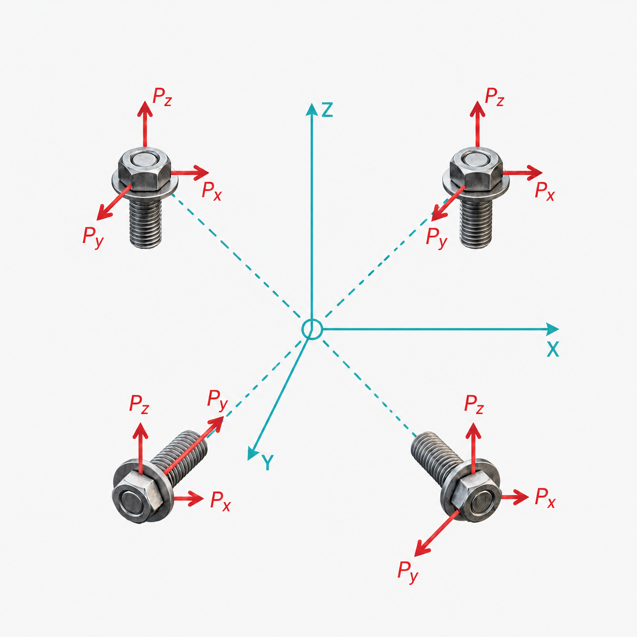
3D Bolt Group Documentation

Complete reference for the 3D Bolt Group analysis tool — coordinate setup, loading inputs, and results interpretation.

Applied Loads

Define the external forces and moments applied to the system. You can specify multiple load cases or components.

Load Definition

Each load consists of a point of application (X, Y, Z), force components (FX, FY, FZ), and moment components (MX, MY, MZ).

  • Point of Application: Forces applied away from the group centroid will induce moments on the bolt group. The tool automatically handles the coordinate transformation.
  • Forces: Axial and shear loads applied at the specified point.
  • Moments: Pure couples or torques applied at the specified point.

Shared Laminate Builder

Laminate Properties

Input Allowables Format

Toggle between Strain (με) and Stress (ksi). Values in the stack and limits will convert on-the-fly.

NameET1 (Msi)EC1 (Msi)ET2 (Msi)EC2 (Msi)G12 (Msi)ν12t (in)σ₁t (ksi)σ₁c (ksi)σ₂t (ksi)σ₂c (ksi)σ₁₂s (ksi)r_c Tens (in)r_c Comp (in)K_br TensK_br Comp
Save as Custom Preset

Save the current material properties under a name so you can reuse them without re-entering values.

Quick Add Ply Angle
Bulk Add Plies
@
Ply Stack 0 plies
Use the quick-add buttons above to build your layup stack.
Total Thickness:0 in