Applied Loads
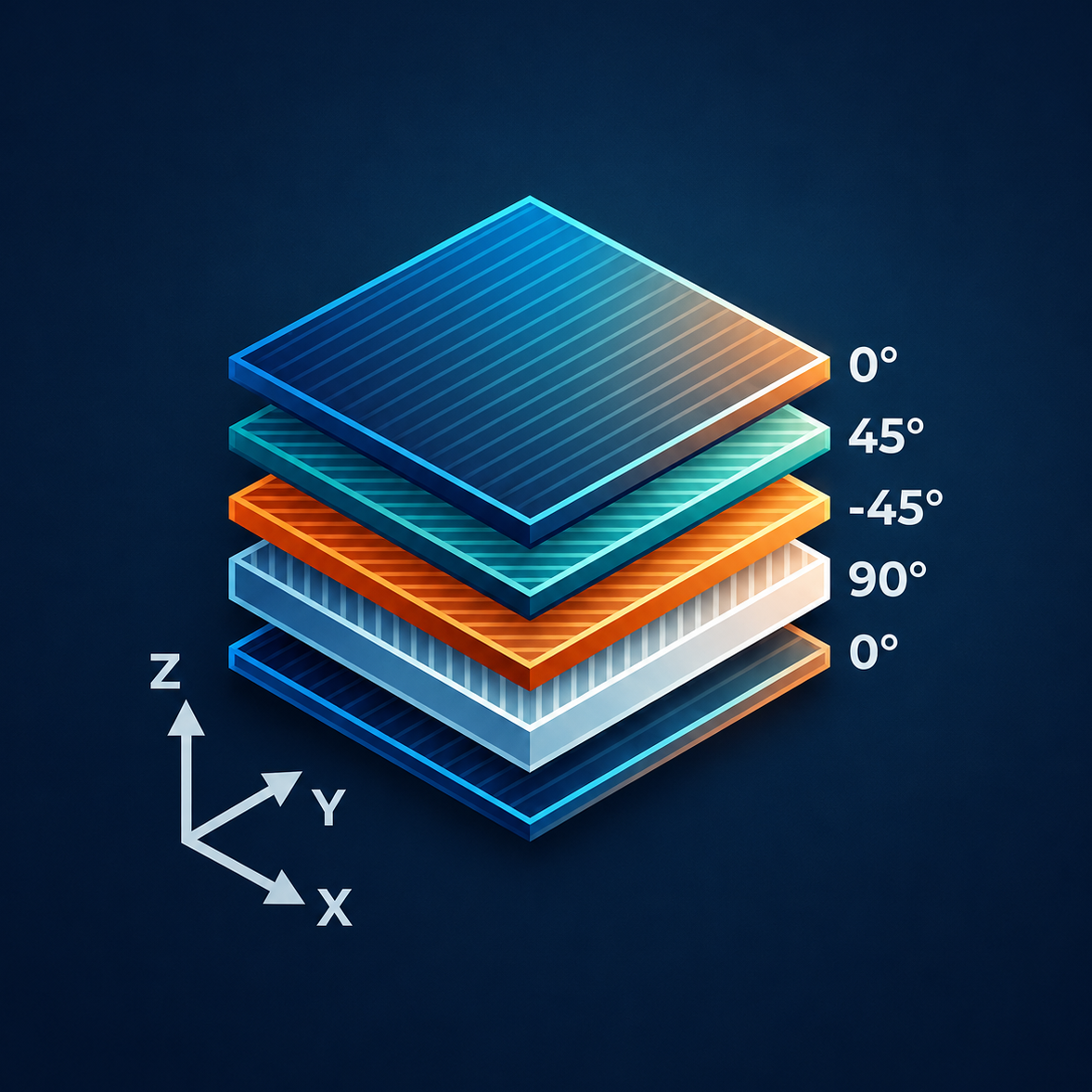
CLT evaluates laminate response to applied force resultants (N) and moment resultants (M). All loads are specified as running loads (force per unit width) or moments (moment per unit width).
Force & Moment Resultants
| Parameter | Units | Description |
|---|---|---|
| Nx | lb/in | In-plane running load in the x-direction |
| Ny | lb/in | In-plane running load in the y-direction |
| Nxy | lb/in | In-plane shear running load |
| Mx | in·lb/in | Bending moment per unit width about the y-axis |
| My | in·lb/in | Bending moment per unit width about the x-axis |
| Mxy | in·lb/in | Twisting moment per unit width |
Load Conventions
Two load sign conventions are supported to match different workflow expectations:
- CLT (Default) — Standard CLT convention where a positive Mx produces tension on the bottom surface (positive z) and compression on the top surface (negative z).
- NASTRAN — NASTRAN convention where the sign of Mx, My, and Mxy is reversed relative to CLT convention. Switching conventions automatically negates the moment values.
Note: Switching conventions flips the sign of all three moment components (Mx, My, Mxy) in-place. The force resultants (Nx, Ny, Nxy) are unaffected.